
I needed to mark where the ailerons get cut, but first I had to make sure I had a perfectly straight trailing edge on the wing (since the aileron measurements are referenced from the trailing edge).
Notice the not so straight trailing edge... that's because when I finished the wing layups, I did a rough trim and moved on...

I took a chalk line and marked a perfectly straight line on the trailing edge...

Look close, the blue line...


Since the chalk line was a bit transparent, I took a straight edge and went over the chalk line with a pencil for a sharper clearer line...

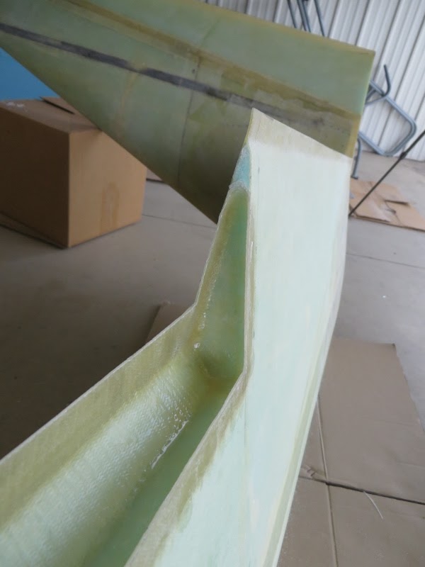
I then made sure I still had proper glass-to-glass contact before trimming...

With the clearances checked, I proceeded to sand the trailing edge up to the line...

With the trailing edge perfectly straight, it was time to mark the aileron cut lines.
The plans give the following:

SPECIAL NOTE:
CP#34 LPC #107 warns us with the following: "Clarification : The root of the aileron should be cut at 90 degrees to the trailing edge along the line on the top skin to the hinge line defined by the 5.9 dimension. This cut is a vertical plane and will not pass through the point on the bottom skin that is defined by the 7.6" dimension."
The biggest takeaway from this is that the 7.6" dimension shown on the bottom inboard surface of the wing is ONLY there to reference and draw the bottom leading edge of the aileron. The aileron inboard edge is cut 90-degrees to the trailing edge. So taking a carpenter's square along the trailing edge of the wing and lining it up with the "same point" as the top surface, will result in a line that does NOT pass through the 7.6" point.

So here I am showing how I measured 7.6" down the BL 55.5 foam joint... used that point to mark the aileron's bottom surface leading edge (blue line)...

BUT pay close attention here... the pencil line in the above picture is NOT the cutline. That was just there to help locate the aileron's bottom leading edge line. The aileron's inboard cutline (bottom surface) is located by drawing a 90-degree line to the wing's trailing edge... and stops where it intersects with the blue line. The picture below shows the actual cutline in red.

With all dimensions and lines marked, it was time to cut the ailerons out! The plans say to cut the top surface 120 degrees pitched aft (or 60 degrees forward, depending on how you look at it). So I made a 60-deg reference block out of foam, and had my buddy site the blade as I made the cut. This worked out great!


The bottom surface cut was easier since it is cut perpendicular to the surface...

We then used a hacksaw blade to make the inboard and outboard edge cuts...

Presto! Aileron cutouts complete!

Of course, all this had to be repeated for the other wing...

With the ailerons cut out... it was time to prep the pockets for the layups.

I used a blade to remove foam along the pocket walls... this blade was perfect since it had an angle to it which created a nice transition from foam to glass...

I intentionally had not applied the peel ply on the pocket walls when I did the wing layups... since I learned from the canard chapter that embedded peel ply isn't so easy to peel off! It's actually a very time consuming process as it tears every inch! So I used a dremel to remove all the micro and prep for a nice glass-to-glass bond!

Showing the inboard rib pocket...

Marked the location of the hinges (since they receive an extra BID ply for reinforcement)...

Showing the outboard rib pocket...

With the pocket prepped, it was time to glass it up! We started by painting plain epoxy on the walls...

And then slurry on the foam... being careful not to put any slurry on the glass surfaces...


3 plies of BID @ 45-deg...

Used the brush to wet everything out one ply at a time... then the extra 1 ply of BID where the hinges will be installed...


I then peel plied any transitions...


1" into the inboard torque tube hole as the plans state.... I should note that I used fiberglass from the pocket layup to fill about half way up the torque tube hole... and then used scraps of BID to complete the rib aft of the torque tube hole's halfpoint... this made it easier to form the glass on the inboard rib...

With everything cured, it was now time to trim things up...

I used the multi tool to trim the edges...

I then sanded everything perfectly straight...

I used a straight edge to assure a perfect trailing edge...


And there you have it!!! Aileron pockets complete! Next up, aileron layups and install!

No comments:
Post a Comment